The Seasons-4 RDS controller will respond to a leak detection from the refrigerant leak sensors to provide a system response for leak mitigation in compliance with the requirements of UL 60335-2-40.
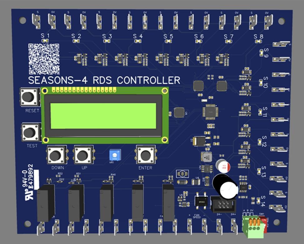
Concept only – actual device may differ
The Seasons-4 RDS controller will have the following features:
Leak Detection Sensor Connections – Up to (14) leak detection sensors may be connected. Two-wire connection with LED at point of connection to light when sensor is in alarm, disconnected, out-of-range or at end-of-life. Any of these conditions will be interpreted as a sensor detection. (24VAC power supply for sensors to be separate from RDS controller).
Supply fan Override enable output – Terminal with LED at point of connection to light when active. Supply fan enable will activate 20 seconds after a sensor detection, and will remain active for 5 minutes (OFF DELAY) after the sensor detection has cleared.
Supply fan Speed Override output – Speed output will be used for applications where required to maintain airflow above or equal to Qmin (default will be 2.5 VDC).
Compressor/Heating Override Lockout output – Terminal with LED at point of connection to light when active. Signal to lock out compressors as well as electric and gas heating. Once activated by a sensor alarm, lockout will remain active for a period of 120 minutes (COMP/HEAT DELAY) after sensor detection has cleared.
NOTE: UV lighting will be locked out along with the compressors, if so equipped.
Damper Override output – Damper override output will activate immediately after a sensor detection, and will remain active for 5 minutes (OFF DELAY) after the sensor detection has cleared.
Zone Override output – Zone override output will activate immediately after a sensor detection to open a VAV boxes or zone valves/dampers, and will remain active for 5 minutes (OFF DELAY) after the sensor detection has cleared.
BAS Alarm Output – Dry contact with LED at point of connection to light when active. BAS output to remain active until all override outputs are clear.
FAULT LED LIGHT – Red fault LED shall light on a sensor detection, led will be cleared by RESET button only.
RESET button – Reset button will clear fault light, only after fan mitigation cycle is complete. RESET button will clear compressor/heating override lockout after fan mitigation is complete.
TEST button – Test button will simulate a system response for a period of 5 minutes to verify all systems are responding as directed by the RDS controller.
LCD DISPLAY – Display will be clear during normal mode of operation (no detection). When a detection has occurred, the number corresponding the sensor location will be shown on the left of the display, with the time since detection displayed on the right-hand side of the display, HHH:MM format. This information will continue to be displayed until the RESET button is pressed.
NAVIGATION BUTTONS – UP, DOWN, ENTER-These buttons will be used to navigate menus to set for the following:
- #SENSORS – Enter number of sensors connected (sensors must be connected sequentially, without skipping numbered inputs)
- OFF DELAY – delay after sensor detection has cleared – Adjustment range is 1 minute to 20 minutes, in one-minute increments; DEFAULT will be set at 5 minutes
- SPEED REF – Speed reference signal – Adjustment range is 0.1 to 10.0 in 0.1 increments; DEFAULT will be set at 2.5 VDC
- COMP/HEAT DELAY – Compressor/heat lockout delay (30 minutes to 300 minutes, in one-minute increments, DEFAULT is 120 minutes.
| REV. 0 | 10.15.2024 |
| REV. 1 | 10.19.2024 |
| REV. 2 | 11.01.2024 |
| REV. 3 | 11.08.2024 |